AvPainter - SL Clothes Design and Preview Tool - Full Version Version 1.7.4
If you're on Second Life or on OPenSim and still have an SL account, it seems you can get this from teh Second Life Marketplace for free. Product page is https://marketplace.secondlife.com/p/AvPainter-SL-Clothes-Design-and-Preview-Tool-Full-Version/166800?id=166800&slug=AvPainter-SL-Clothes-Design-and-Preview-Tool-Full-Version. You have to rez it in a sandbox that runs scripts. I haven't got mine to work, yet.
#SecondLife #OpenSimulator #Windows
Showing posts with label opensimulator. Show all posts
Showing posts with label opensimulator. Show all posts
Sunday, November 25, 2018

Wednesday, March 7, 2018
The big thing about this new release is that it adds decent OS only support.
The big thing about this new release is that it adds decent OS only support.
#windows #opensimulator
Originally shared by Lelani Carver
This will be useful to a lot of people in SL and OS! Fred Beckhusen will know who.
http://www.hypergridbusiness.com/2018/03/new-lsl-editor-released/
#windows #opensimulator
Originally shared by Lelani Carver
This will be useful to a lot of people in SL and OS! Fred Beckhusen will know who.
http://www.hypergridbusiness.com/2018/03/new-lsl-editor-released/
Monday, January 15, 2018
Here's the KOKUA viewer (for OpenSim) running on the NUC monitor.

Here's the KOKUA viewer (for OpenSim) running on the NUC monitor. I think I might need to adjust the GUI size - what do you think?
#OpenSimulator
Wednesday, March 8, 2017
Leveller for Open Simulator (part 5)
Merging Documents in Leveller
This tutorial looks at merging two terrains using Leveller (a powerful 3D terrain editor for windows from Daylon Graphics) for later use in OpenSimulator (Opensim). This tutorial assumes that you've read Part 4. If you haven't, please do that before reading on.We'll be using terrain.party to generate 16bit PNG terrain files for us. This online application allows the user to select a portion of the map of the earth and generate a series of PNG files that you can import into Leveller. The reasons for using this online application are:
- It's free to use;
- PNG format can be viewed as an image;
- Files can be generated from anywhere on the Earth ; and
- It's simple to use.

You can search by name for a location, zoom in or out, and scroll around the map of the Earth by dragging the mouse. You can also decide which which overlay to use, though the two USGS options only work in the USA and territories. You can also decide how large the selection area is and place that where you want, though it doesn't move unless either you manually move it, or your text search moves the map to a location.
Tenerife Island
Tenerife Island was used an an example of creating contours with shapes in Part 3. Here's a map of it... |
| By Oona Räisänen (Mysid) - Self-made in Inkscape.Topographic data from the Shuttle Radar Topography Mission (SRTM) as modified by CGIAR-CSI.Bathymetric data from SRTM30_PLUS.Relief shading was derived from SRTM data in GIMP.Roads and place names manually retraced from the OpenStreetMap, originally by OpenStreetMap contributors., CC BY-SA 3.0, https://commons.wikimedia.org/w/index.php?curid=11100572 |

The main difference between this and the previous two examples in Part 4, is that the island is too large to fit into the largest selection size of terrain.party which is 60km. Now one solution to this issue would to find a different source of map data for the island. For this example however, we'll do a work around, of patching together the heightfields from two overlapping PNGs.
To do this, first we'll expand the selection area to 60km and download from first the South West of Tenerife, and then from the North East. There should be an overlap as seen below:

The two selections above are (as taken from the Readme files of each downloaded zip:
Tenerife 60km SW
http://terrain.party/api/export?name=Tenerife+60km+SW&box=-16.355525,28.468774,-16.968654,27.929788
Elevation range: 0 through 3696 meters
Tenerife 60km NE
http://terrain.party/api/export?name=Tenerife+60km+NE&box=-16.025059,28.768499,-16.639940,28.229514
Elevation range: 0 through 3616 meters
The maximum heightfields vary because one of the maps has height terrain than the other. The scale for each is 1081 / 60000 or 0.0180166666666667 or 2%! We can scale the maximum heightfields down proportionally to 73.92 for Tenerife 60km SW, and 72.32 for Tenerife 60km NE.
Going through the process that we did for both St. Helena and Rottnest, after inspection well use the Merged versions of the PNGs for each: Tenerife 60km SW Height Map (Merged).png and Tenerife 60km NE Height Map (Merged).png. We'll import each with correct elevation ranges, accept the large map, and select ALL of it. We then have two maps:

Each of these documents is 1081×1081 in size, and their heightfields should be correctly scaled so that when we paste them together, there should be a smooth join. The guidelines on each have been changed to show only 1m and 256m, and the difference in what shows depends on what zoom you have. Before we do anything else, we'll save these documents with their default names as Import of Tenerife 60km SW Height Map (Merged).ter and Import of Tenerife 60km NE Height Map (Merged).ter!
Merging maps
There are two ways to merge these two documents together. The first is to enlarge one of the documents by using Edit > Pad and then copy and paste the terrain of the other document into it. You could also create a new document using File > New and make sure it has enough width and breadth, and then copy and paste both documents into it. In either case, In the first case I'd recommend saving a copy of the padded document with a new name via File > Save As, so that if anything goes wrong, you still have an original version of that document if anything goes wrong.We'll do the padding option in this example, and use Import of Tenerife 60km SW Height Map (Merged).ter as the document to be padded. Doing Edit > Pad (or Shift + E) with that document selected brings up...
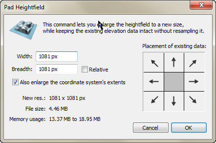
We should select the bottom left box because that's roughly where that document's terrain will sit in the final merge. This will mean that no pixels will be added to the left or bottom of the document. The next question is how much to expand the document? We could just play save and double the Width and Breadth, and crop the document later. Looking at the maps above, there should be about an extra 512px to both dimensions. If we add 600px that gives a margin or error. Either way we may need to crop or pad the document afterwards, to make a document width dimensions evenly divisible by 256m, and hence suitable for export to Opensim. The help page on this dialog says to ...check Also enlarge the coordinate system's extents if you want the ground extents to increase to take into account the new areas. This will preserve gridpost spacing. Otherwise, gridpost spacing will decrease since more heightfield pixels are using the extents. Normally you'll want to enlarge the extents as this will preserve the spatial measures of heightfield formations. Seems like a good idea. So we'll try this:
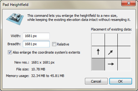
...and this is the result:

So far so goo. Now would be a good time to Files > Save As this to something like Tenerife (Merged Terrain).ter. Now we swap to Import of Tenerife 60km NE Height Map (Merged).ter and do a Selection > Select Elevations. If we enter -11 to 0 in the following dialog...
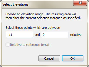
...and the select Replace and OK the that on the following dialogue (if it appears), we get the following selection:

Everything but the land is selected. If we use Selection > Invert (or Ctrl + I) we invert the selection and get this...

...which is the selection we want. Now we use Edit > Copy (or Ctrl + C) on this selection and then swap to the padded document. After doing Edit > Paste (or Ctrl + V) we should see this:

The selection's been pasted to the padded document, and the Select tool is now active. This is currently a Floating Selection, so you can move it about first, and when happy with the position, Defoat it to be part of the terrain below. Until you defloat this, you can still press Delete and erase the selection if you want to (maybe you realised you've copied the wrong selection). Using the scroll wheel on your mouse will zoom in and out on the map, which is handy for matching up terrain.

This looks about right, so we'll use Selection > Defloat > Replace, which will replace the terrain underneath with the floating selection. The result is...

...which is not quite right! What's with the dark lines? Looking at the scene, we see:

Oops, the terrain looks slightly off, and the lines are showing the edge of the paste where the heights don't match. We have several options. We could do an Edit > Regress To to restore the map to the previous state, and return the floating selection. e.g.:
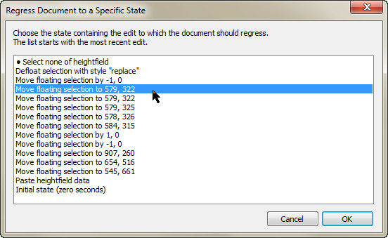
Instead of using the mouse to move the floating section, you can just use the arrow keys to move it one pixel at a time (though you need to time this correctly or you'll overshoot). It may just mean you need to move the floating selection a few pixels horizontally or vertically. If the next attempt doesn't work you can regress and try again. It could be that our scaling is slightly out as well, and you could try importing the PNG again with a slightly lower maximum height.
You can also choose other options than Replace when defloating the selection. Use Edit > Regress To as shown above, but when you Defloat the selection you might try Average instead. This will be fine when defloating over similar parts of the map, but defloating over zero or blank areas, not so much. Another option is to play around with the selection before you copy it. Try doing Selection > Shrink four times and then Selection > Feather with 4px. Or you can Selection > Blur it as well. Then when pasting a slightly smoother edge might result.
Alternatively you could Regress as above, swap to the other map and use Filter > Elevate with Lower and 1, and then copy the altered selection. If the paste is 1px out in elevation, this might be an easier way to change that.
Or it might not. In the end you might just need to use the Blur tool and Smudge tool to soften the edges manually. Of course that's going to reduce accuracy in relation to the real world terrain, but if you can't see the creases it's all good. Here's the result of some blurring and smudging. There's a hint of line, so some more work needs to be done.

Assuming that's done, we still have some cleaning up to do. Here's what the whole map looks like, with the Contours toggled off:

The padded area has a height of -18, and the original no data (ocean is zero). You need to make this standard. Easy to do using the Magic wand tool. Select some part of the padded area, and then select some of the zeroed are while pressing Shift. That selects everything that isn't the island:

You could also do a Selection > Select Elevations and use .1 and 400 as values. That will select everything over zero. Then press Ctrl + I to invert the selection and we get the same result. Either way, if we press Delete then all the selected area becomes -18.

Finally we'll use Filter > Elevate using Lower and 2 to drop everything by 2m, with the ocean floor being at -20 (the lowest you want for most documents getting exported to Opensim. It now looks like:

Looking better, and a lot better than my result in Part 3!
Monday, March 6, 2017
I have a first draft on a tutorial about importing real life geography into Leveller, and later into OpenSimulator.
I have a first draft on a tutorial about importing real life geography into Leveller, and later into OpenSimulator. I have two more examples to add, but they might not get done until Thursday.
#daylonleveller #opensimulator
#daylonleveller #opensimulator
Maybe one could also use mesh created in Unity for this?
Maybe one could also use mesh created in Unity for this?
#blender #opensimulator
https://fxualeducation.wordpress.com/2016/09/01/virtual-avebury02/
#blender #opensimulator
https://fxualeducation.wordpress.com/2016/09/01/virtual-avebury02/
I've updated this tutorial to show how to import vector files as shapes, and renamed it, as it was really about...
I've updated this tutorial to show how to import vector files as shapes, and renamed it, as it was really about using vector shapes to make terrain. The real life terrain maps were used because it was easy to demonstrate creating contours against them.
#daylonleveller #opensimulator
#daylonleveller #opensimulator
Saturday, March 4, 2017
Rather than do the housework, I made a new tutorial about using Leveller for Opensim.
Rather than do the housework, I made a new tutorial about using Leveller for Opensim. This one explains how to make heightfields from shapes.
#daylonleveller #opensimulator
#daylonleveller #opensimulator
Leveller for OpenSimulator (part 3)
Making terrains using shapes in Leveller
This tutorial looks at creating terrains using shapes in Leveller (a powerful 3D terrain editor for windows from Daylon Graphics) and OpenSimulator (Opensim). This part explains how to create heightfields in Leveller from existing image maps, using contours and shapes. We can then export the terrain to OpenSim (see part2). Before you read this tutorial, you should read both Wikipedia:Contour Line and Topographic Maps (Topo Maps) and Contour Lines for an understanding of what contour lines are, if you don't already know.Tenerife example
You can, with a little practise, make your own maps in Leveller. For the purpose of this tutorial however, we'll make an island based on a topographical map of Tenerife, as found on the Wikipedia., which can be shared and remixed under the Creative Commons Attribution-Share Alike 3.0 Unported license.
Here's how the real Tenerife looks from space. There's lots of detail here, but for now a flat map will be a start.


We are not going to attempt a 1:1 scale recreation of this island. It measures roughly 40×30 km and would need about 157×120 256m² regions! Instead we're interesting in the shape and the contours shown. We will create a heightfield measuring 512m×512m, and you can export this to either a single 512m² region that matches those dimensions, or to a 2×2 grid of 256m² regions.
Preparing the image
The first step will be to download the image and prepare it as a texture for Leveller. Follow the link above, select Download and on the popup dialog select 1024px (rather than only 512px, so that when you you look at it outside of Leveller, you can see as much detail as possible), as shown below.
Your browser tab will then show an image of that resolution wide. You can then via your browsers save 1024px-Topographic_map_of_Tenerife-en.svg.png to a convenient location on your PC. Once that's done, open this file in whatever bitmap graphics editor you use (GIMP, Photoshop, et cetera). Change the Canvas size so that it is now 512x512, and the original image is centred on this. Select darkest blue tone (the one shown on the legend between 3500m - 4000m) and fill the new parts of the canvas with this. Save the result as Telerife-Texture.jpg, and you should have something like this:

The canvas was changed to make the image square and match the shape of the heightfield. The image is now ready to use as a heightfield texture in Leveller.
Setup Leveller Document
Open Leveller, and use File > New to create a 512×512 document with local coordinates. Use Navigate > Gridlines, and remove all allowed spacings except for 1 m; then add 256 m (both steps are shown in Part 1 and Part 2). Select File > Texture, and you should see the following dialog:

Select the Change button, and the Change Heightfield Texture Bitmap dialog appears. Change Format to JPEG bitmap and then select the Telerife-Texture.jpg file as created in the above steps. Select OK twice and the texture will be loaded into Leveller. Even though this is the case, nothing extra will be displayed yet! You need to do two things. The map pane should have a panel above it that looks like this (shown single sized):

Most of these buttons toggle viewing settings for that pane. For this tutorial we'll have Gridlines and Gridline Captions always on. If Heightfield texture is off, the texture won't show draped over the map. If the Texture Opacity button is depressed, the texture drape will be translucent. Vector shapes toggles seeing the the shapes on the map pane, and Vector drape texture toggles seeing extra colours/textures associated with each shape.
We'll toggle to Heightfield texture on. But still nothing's happening. That's because the entire heightfield is at 0 m, which is the default water level. If we go to Filters > Elevate, and raise the document by 1, the map should look like:

At this point, save the document as Tenerife.ter (or, as I mistakenly did, Telerife.ter, D'Oh!), and we're ready to add shapes as contours.
Adding Shapes
We're now going to create a set set of points using the the Vector Tools. There are found on their own toolbar, usually positioned at the upper right portion of the work area. The toolbar looks like this:

The Pointer tool is used to select anchor points, lines, and entire paths, and then to move or modifying and/or moving those. The Pen tool, like similar named tools in Illustrator and other vector editors, allows you to draw a path which might be either open or closed (both end points are connected), by creating anchor points and corner handles. You can also create a marker with it, which is a single point. The Scissors tool not only allows you to cut a closed path into an open path, but also to add extra anchor points along a path. The Rectangle and Ellipse tools create closed paths which match those shapes (mainly by adjusting where the anchor points and corner handles are created). The Rotate, Scale, Flip/Mirror and Slant tools adjust entire paths.
What we'll be doing is creating closed and open paths, and also markers, that we can assign a height value to, and later generate a heightfield via the Shapes > Heightfield from Points option. Before we start we should toggle Vector Shapes to on (or we won't be able to see what we're doing) but leave Vector drape texture to off (otherwise these might obscure what we can see). Use the arrow keys and Zoom map tool to zoom into the area where we'll start making a shape. We'll be making a closed shape to match the outline of the island, and you should see something like this:

Select the Pen tool, and left-click at a point on the coastline as shown on the draped text. Move the cursor to another point on that coastline and left-click again. You should see something like this (minus blue and red arrows):

The blue arrows point to the first and second anchor points created by the left-clicks. The line segment between them is highlighted, and the red arrow points to the Pen cursor (which is currently over a height of 1m). Two simple left-clicks will create two points and a straight line between those points, but if you left-click and drag, you can bend the line. We'll create another line segment by moving the pen cursor to the coastline right and below where it is now, and do a left-click drag. It might look like this:

The blue numbers show the order in which the points have been made, and the red arrows show the control handles. Points 1 and 2 were smooth points, and 3 was created as a corner point, which is why it has control handles. It really doesn't matter if you don't get this right when initially creating the path, as you can go back and edit the path later, moving or adding (or deleting) extra points, and changing how the lines bend from an anchor.
The line between 1 and 2 looks a bit too straight, so we'll add some new points to and and edit then to curve the line. First we'll add extra points. Change to the Scissors tool and left click on where the line between 1 and 2 overlaps the coastline. You should see:
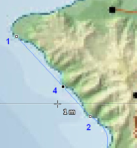
So point 4 has been added to that line. Of course it's a smooth point so the line segments on either side of it are still straight. If we moved 4, those segments would still be strain, but still pointing to 4 somewhere else. Instead, we need to change 4 from a smooth point to a corner point. Swap to the Pointer tool. The point is already selected, so press the Ctrl + left click on point four. It changes to a corner point and now has two control handles:
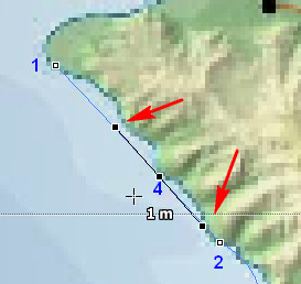
All very well but the line's still straight. You need to select one of the control handles and fiddle with it's location. The angle and distance from it's corner point (4) determine the bend and curve of the line. We'll fiddle with the handle close to point 1. The result might look like this:
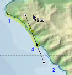
Although it's hard to see against the texture drape, the line's now curved and matches the coastline better.Note how the opposite control handle matches the angle of the control point moved. this is the default but you can change this by selecting the corner point (4) again, and doing another Ctrl + left click. Now, when you move either control handle the other handle attached to that point is unaffected. We'll do this, and then fiddle about with the other handle for a better fit. Hopefully it looks like this:
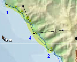
As you can see the control handle's now independent from the other handle's position. However, we still have a straight line between 4 and 2! Select point 2, and Ctrl + left click it (which you might need to do twice) to change it to a corner point. We now have:
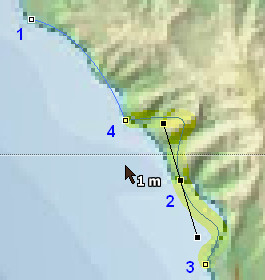
So now the 2 is a corner point and has handles, but the default positions of those needs to be adjusted.Also, if you don't Ctrl + left click again, they'll affect each other. We'll do that and fiddle around until we get:
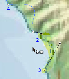
Now the 2-4 line segment needs to be fixed. We could just select point 4, and then the handle, and then point 2, and then the handle, but instead we can also select that line segment, and that will show both handles that determine its shape, like this.
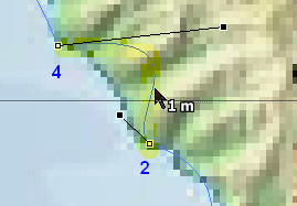
More moving control handles to be done and maybe moving one of the points. This is how the finished (for this part of the coast) shape looks...

...and that's only five points! To repeat, it's often better to draw a rough path but a complete one first, and then edit that path afterwards. The above coastline looks fine, but in making it so we broke the momentum of drawing the full path. To complete this we'd draw a new path, select two end points and do a Ctrl + J to join them together. That finished coastline might look like this:

Now with a strong texture drape it may be difficult to see a shape. You can play around with toggling Texture opacity and Selection opacity (or even toggle off Heightfield texture entirely) the to make shapes clearer. When you are initially creating the shapes, you need to see where the original lines are, but after you've created those you may not always need the texture at all.
The other contours
Of course the coastline is only one contour. In addition to this, three are higher elevations in the island's interior, and lower ones in the surrounding ocean. After a lot of extra editing, we have basic set of contours like those shown below:
Some of the shapes go outside of the map area. That's allowed, but a heightfield will only be generated within the map are. The outer rectangle (which could just as easily been an ellipse or or irregular shape) is used to mark a lowest level of the map, in relation to the contours within it. As yet, none of these shapes have a height value.
We're making this terrain to use in Opensim. In general the lowest height in that is zero, and the default sea level is set at 20m, and a maximum height in the thousands. In Leveller and other 3D terrain editors, the water level often defaults to zero. we'll keep that convention, as this is compensated for in the Export Tiles dialog box (see Part 2) with a default 20m added to the heightfields of exported tiles. So, the water level is 0, and the relative lowest level would be -20. If we set the elevation of the outside rectangle to -19 and all the other shapes have a higher elevation than that, then we won't have any issues when exporting to Opensim.
To set the elevation of a shape, first select that shape, and then Right-click to bring up the context menu, as per below:

Select Properties (you can also select Shapes > Properties on the menu) and the Properties of Selected Shapes dialog will pop up. We'll enter -19 in the Elevation field, and then select OK...
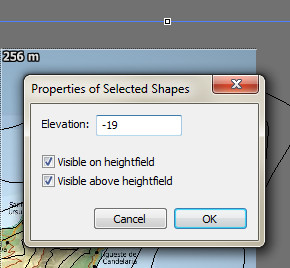
...so now we have our first shape with an elevation. We'll repeat this step on the remaining shapes. The image below shows the values I've assigned to them (though this usually wouldn't show on the map directly):

Remember that the terrain isn't really to scale (otherwise the relative elevations of the island might seem slight). The values I've chosen should highlight the creation of heightfields by using shape. Selecting the Pointer tool, either press Ctrl + A, or select Selection > Select All. Then select Shapes > Heightfield from points. The result on the map (I've toggled the Heightfield texture off for clarity) should look like this...

...and the scene pane should look a bit like this:

Don't like the elevations on the island? There's an easy way to change that.First, manually use the Pointer tool to select all the shapes used for the island:

Then go to Shapes > Modify > Span. The Spans Selected Vector Shapes dialog will appear and indicate the current range of all shapes selected.

We'll change the first value to .4 and the second to 32. Select OK, and then do another Shapes > Heightfield from points. The scene will now look something like...

The edge around the island is because we didn't select any of the ocean shapes, and the height outside the island has dropped to -19! To correct that, simply select ALL shapes (as explained above) before generating a heightfield from shapes.
Further Editing
This is just the start of creating the heightfield. In addition to using closed shapes as shown above, you can add lines and markers of various elevation to create different effects. You could add more points to improve the coastline shape, or any of the other shapes used. You can also use any of the brush tools to manually add of edit the heightfield, but that's another tutorial.
Exporting to Opensim
When you're satisfied with the result, export it to OpenSim. See Part 2 for how to do that. Here's what the above looks like imported into a 2×2 256m² demo grid:

...and here's the view:

This is still only a vague approximation of Tenerife. If you want to see something more accurate, go to Part 5!
Simpler Stuff
The above example looks complex (though the final result is fairly simple). I used Tenerife as an example because it was an interesting shape, and having a map texture from real life meant that we could judge our progress with the original. , But contour modelling doesn't have to be complex. The following document was used in Part 2. It's not based on real life maps, and is far simpler!

This 256x256 document was created by creating eight shapes, giving each a height (as shown on the map at right and then selecting all shapes followed by executing a Shapes > Heightfield from Selected Points command. Finally the water level was set using Edit > Water Level > Elevation to 20 (and when exported using Export-tiles, the height adjustment would be zero). Only eight shapes.
Importing shapes
You also don't have to create your own shapes to make a terrain, you can import them instead! Leveller will import the following vector formats: Adobe Illustrator, Arc/Info ASCII, Arc/Info Binary, BNA, CSV, DGN, DXF generalized, DXF polylines, ESRI shapefile, GeoConcept, GeoJSON shapefiles, GML,GMT, PS, IHO, Keyhole Markup, MapInfo TAB/MIF/MID, PGeo, EPInfo REC, SDTS TVP, SVG, TIGER/LINE, UKOS NTF, and X-Plane/Flightgear.
Here's an Illustrator document (Twins Contours 00.ai) I made to map the contours of a local grid that measures 6×5 1024m² regions (6144×5120px):

To import this, we'll first create a new document sized. 6144×5120px. Then, We'll run Filters > Elevate and raise the whole map to .5m. You should now see (using the Earth to Water Colour Map) a blue map. Now go to Shapes > Import shapes and the Import Vector Shape data dialog will pop up:

We'll select the Adobe Illustrator option, and find that file. Things should look like this:

Pressing OK however, only gets us this error message:

Leveller imports Adobe Illustrator, but it needs to be in Illustrator 8 format. So, we go back to Illustrator (I'm using CS6, it may be different in the CC version) and do a File > Save a Copy. Give the copy a name to identify it (Twins Contours 00 8.ai for example) and select the following options on the next dialog:
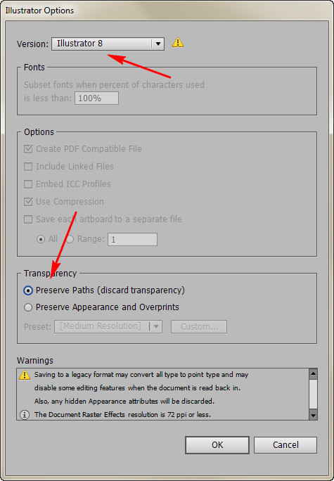
Jumping back to Leveller, select Shapes > Import Shapes again, but this select the file. Click OK, and after a delay you will see the Import Shapes from <filename> dialog:

For now we'll just select OK and proceed with the import. We wait until that's done, and should see something like this:

Your mileage might vary on this. At best, the vectors will be imported with a height value attached to them, but that value has to come from somewhere, and may not be in the program that created the vectors. Because of the wide variety of formats accepted, you can use open source (and free) programs like Inkscape to create SVG files. In Illustrator, I could have also saved the copy in SVG format as well. Use what makes sense to you.
Next time...
Part 4 of this series will deal with importing real geographical data into Leveller and preparing it for Opensim.
Subscribe to:
Posts (Atom)