Topics

3d 3D Resources and Applications 3Deditortests 3dmodeling 3dmodelling 3dprinting 3dterrain abobe illustrator AC3D academic accessibility Addon adobeillustrator Adoboe aeontimeline Alphabet am amigaOS anamorphic android Android animation annoyances Anxiety ANYmal apple application Application References ApplicationReferences Applications apps AprilUpdate Archie] architecture archivefootage archives art ascii-art assistants astronomy atari Australia AutoRun b3d BBCNews Bipdeal blender Blender Blinded by Science! BlindedbyScience BostonDynamics braille Brave BSD c128 c64 cellPhoneTowers Centric chemistry Chrome chromeOS Clipstudio coding comic ComicNarrative comics commodore Computer Madness ComputerMadess ComputerMadness computers computing ConEmu console Consoles contours Copernicus Daria daylonleveller depopulation design designer diagrams digitalcomics digitalpainting digitaltag discovery_of_pulsars DIY docear doctorwho DOD drawing drawingsoftware drwho dualboot Earth ebooksfree ecosystems Edge Edit editing editors Electromagnetic Electrons emailclient endniote Energy Engineer Engineering excel exegesis exidy exporting facebook facebooksucks fake Fault fileutility firefox Firefox firefox57 Firestorm Flame flash free freeBSD freemium freeplane freesoftware freeware Friendica future Galileo generator Geocentric geos Ghost World ghosttownphotography GIF github Google google+ googleplus googleplussearch googleplustips graphics GRUB gui harddrive HarrissSpiral hashtag hashtags heightfield Heliocentric help HighandLowWeirdness history history_of_science HistoryOfScience homecomputer HomeNetwork import importing infographic inmoov interactivestory Intermittent internet Internet Stuff InternetStuff INternetStuff Ions iOS IOS ipad iphone ironman ISurfSocial java javascript Jenny Everywhere JocelynBellBurnell JudgementDay julesverne Knowhow kodi krita Krita LAS LASOpensimulator LASRandom LASTechnology Laura Ess Laura's Art LauraEss leveller levitation Libraries libreoffice linux Linux LinuxSnap LiveJournal mac macOS MacOS macOSX mangastudio5 mangastudioex5 maps MapSCII Match math mathart mathematics MaxOSX MediaPC memorial mesh MeWe microsoft microsoftexcel Microwave mindmapping mindmaps Mint MintKDE mobile modelrailways Molecules mono Motors mozilla Mozilla msdos MSNFeed msx Music NAS nasa natron NBN ncp NetNeutrality netradio Network NetworkStorage newzealand NikolaTesla nodejs npm NUC nz oldmachinery online onthisday open opensim opensimulator opensimulator terrain OpensimulatorLAS opensource opensourcesoftware openstreetmap Opera opml Orbit os outliner PaintToolSai PanicAttack password pc2 penrosetriangle pets photography photoorganizer photoshop physics Physics Planets plant plants Plasma png Podcast polyhedron Privacy processing programming projectmanagement PSRB1919 publicdomain Push pyromagnetic_electric_generator Q4OS quadrupedrobot quantum_mechanics Radiation radio RandomLAS raspberrypi reallife recovery RecRoomPC RemingtonRand research Retro retrocomputing reversenostalgi robos Robot robotic robotics Safari Sai SAVENETNEUTRALITY scalextric scapple science scienceeveryday ScienceGIF scitech Scooby Do ScoobyDoo screencapture Scrivener search searching SecondLife secondsgrid SecurityBreach SelfRighting server shapes sharing shopping simonastick Singularity sketchup SKYNET smartphone SocialMedia software Solar SolarSystem sorcerer sound sounds space spaceshuttle spectravideo Standing startrek steampunk strawhouse StudioPC subscription sweethome3d Synology tablet tags taskmanagement Technology TechnologyLAS Technomania tedtalks Terminator terrain terrain.party texteditors TextFormatting textures TheFederation thunderbird todolist Tor trees TripleJ trolley tutorial twt UI UNIVAC universe update updates USA USB3 utility vector-tiles vectoreditor vectors vfx video videoediting videorecording viewer vintagecomputing Vivaldi vocorder Walking web Web webbrowser webcam webdevelopment werner_heisenberg WesternAustralia Widows Win10 Win10Install win7 Win7 windows Windows Windows10 Windows64 windows7 WindowsUpdate Wings3D WomensDay worldmap XnViewMP xport
Showing posts with label tutorial. Show all posts

Saturday, March 4, 2017

Leveller for OpenSimulator (part 3)

Making terrains using shapes in Leveller

This tutorial looks at creating terrains using shapes in Leveller (a powerful 3D terrain editor for windows from Daylon Graphics) and OpenSimulator (Opensim). This part explains how to create heightfields in Leveller from existing image maps, using contours and shapes. We can then export the terrain to OpenSim (see part2). Before you read this tutorial, you should read both Wikipedia:Contour Line and Topographic Maps (Topo Maps) and Contour Lines for an understanding of what contour lines are, if you don't already know.

Tenerife example

You can, with a little practise, make your own maps in Leveller. For the purpose of this tutorial however, we'll make an island based on a topographical map of Tenerife, as found on the Wikipedia., which can be shared and remixed under the Creative Commons Attribution-Share Alike 3.0 Unported license.


Here's how the real Tenerife looks from space. There's lots of detail here, but for now a flat map will be a start.


We are not going to attempt a 1:1 scale recreation of this island. It measures roughly 40×30 km and would need about 157×120 256m² regions! Instead we're interesting in the shape and the contours shown. We will create a heightfield measuring 512m×512m, and you can export this to either a single 512m² region that matches those dimensions, or to a 2×2 grid of 256m² regions.

Preparing the image

The first step will be to download the image and prepare it as a texture for Leveller. Follow the link above, select Download and on the popup dialog select 1024px (rather than only 512px, so that when you you look at it outside of Leveller, you can see as much detail as possible), as shown below.


Your browser tab will then show an image of that resolution wide. You can then via your browsers save 1024px-Topographic_map_of_Tenerife-en.svg.png to a convenient location on your PC. Once that's done, open this file in whatever bitmap graphics editor you use (GIMP, Photoshop, et cetera). Change the Canvas size so that it is now 512x512, and the original image is centred on this. Select darkest blue tone (the one shown on the legend between 3500m - 4000m) and fill the new parts of the canvas with this. Save the result as Telerife-Texture.jpg, and you should have something like this:


The canvas was changed to make the image square and match the shape of the heightfield. The image is now ready to use as a heightfield texture in Leveller.

Setup Leveller Document


Open Leveller, and use File > New to create a 512×512 document with local coordinates. Use Navigate > Gridlines, and remove all allowed spacings except for 1 m; then add 256 m (both steps are shown in Part 1 and Part 2). Select File > Texture, and you should see the following dialog:


Select the Change button, and the Change Heightfield Texture Bitmap dialog appears. Change Format to JPEG bitmap and then select the Telerife-Texture.jpg file as created in the above steps. Select OK twice and the texture will be loaded into Leveller. Even though this is the case, nothing extra will be displayed yet! You need to do two things. The map pane should have a panel above it that looks like this (shown single sized):


Most of these buttons toggle viewing settings for that pane. For this tutorial we'll have Gridlines and Gridline Captions always on. If Heightfield texture is off, the texture won't show draped over the map. If the Texture Opacity button is depressed, the texture drape will be translucent. Vector shapes toggles seeing the the shapes on the map pane, and Vector drape texture toggles seeing extra colours/textures associated with each shape.

We'll toggle to Heightfield texture on. But still nothing's happening. That's because the entire heightfield is at 0 m, which is the default water level. If we go to Filters > Elevate, and raise the document by 1, the map should look like:


At this point, save the document as Tenerife.ter (or, as I mistakenly did, Telerife.ter, D'Oh!), and we're ready to add shapes as contours.

Adding Shapes


We're now going to create a set set of points using the the Vector Tools. There are found on their own toolbar, usually positioned at the upper right portion of the work area. The toolbar looks like this:


The Pointer tool is used to select anchor points, lines, and entire paths, and then to move or modifying and/or moving those. The Pen tool, like similar named tools in Illustrator and other vector editors, allows you to draw a path which might be either open or closed (both end points are connected), by creating anchor points and corner handles. You can also create a marker with it, which is a single point. The Scissors tool not only allows you to cut a closed path into an open path, but also to add extra anchor points along a path. The Rectangle and Ellipse tools create closed paths which match those shapes (mainly by adjusting where the anchor points and corner handles are created). The Rotate, Scale, Flip/Mirror and Slant tools adjust entire paths.

What we'll be doing is creating closed and open paths, and also markers, that we can assign a height value to, and later generate a heightfield via the Shapes > Heightfield from Points option. Before we start we should toggle Vector Shapes to on (or we won't be able to see what we're doing) but leave Vector drape texture to off (otherwise these might obscure what we can see). Use the arrow keys and Zoom map tool to zoom into the area where we'll start making a shape. We'll be making a closed shape to match the outline of the island, and you should see something like this:


Select the Pen tool, and left-click at a point on the coastline as shown on the draped text. Move the cursor to another point on that coastline and left-click again. You should see something like this (minus blue and red arrows):


The blue arrows point to the first and second anchor points created by the left-clicks. The line segment between them is highlighted, and the red arrow points to the Pen cursor (which is currently over a height of 1m). Two simple left-clicks will create two points and a straight line between those points, but if you left-click and drag, you can bend the line. We'll create another line segment by moving the pen cursor to the coastline right and below where it is now, and do a left-click drag. It might look like this:


The blue numbers show the order in which the points have been made, and the red arrows show the control handles. Points 1 and 2 were smooth points, and 3 was created as a corner point, which is why it has control handles. It really doesn't matter if you don't get this right when initially creating the path, as you can go back and edit the path later, moving or adding (or deleting) extra points, and changing how the lines bend from an anchor.

The line between 1 and 2 looks a bit too straight, so we'll add some new points to and and edit then to curve the line. First we'll add extra points. Change to the Scissors tool and left click on where the line between 1 and 2 overlaps the coastline. You should see:
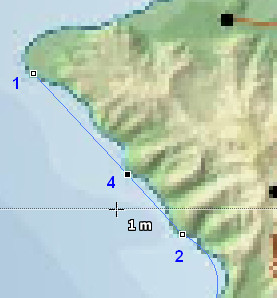


So point 4 has been added to that line. Of course it's a smooth point so the line segments on either side of it are still straight. If we moved 4, those segments would still be strain, but still pointing to 4 somewhere else. Instead, we need to change 4 from a smooth point to a corner point. Swap to the Pointer tool. The point is already selected, so press the Ctrl + left click on point four. It changes to a corner point and now has two control handles:
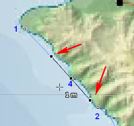


All very well but the line's still straight. You need to select one of the control handles and fiddle with it's location. The angle and distance from it's corner point (4) determine the bend and curve of the line. We'll fiddle with the handle close to point 1. The result might look like this:
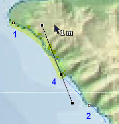


Although it's hard to see against the texture drape, the line's now curved and matches the coastline better.Note how the opposite control handle matches the angle of the control point moved. this is the default but you can change this by selecting the corner point (4) again, and doing another Ctrl + left click. Now, when you move either control handle the other handle attached to that point is unaffected. We'll do this, and then fiddle about with the other handle for a better fit. Hopefully it looks like this:
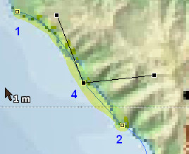


As you can see the control handle's now independent from the other handle's position. However, we still have a straight line between 4 and 2! Select point 2, and Ctrl + left click it (which you might need to do twice) to change it to a corner point. We now have:
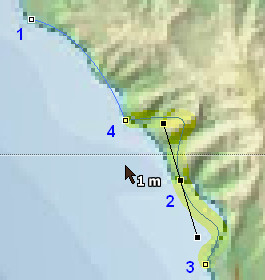


So now the 2 is a corner point and has handles, but the default positions of those needs to be adjusted.Also, if you don't Ctrl + left click again, they'll affect each other. We'll do that and fiddle around until we get:
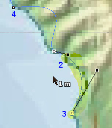


Now the 2-4 line segment needs to be fixed. We could just select point 4, and then the handle, and then point 2, and then the handle, but instead we can also select that line segment, and that will show both handles that determine its shape, like this.
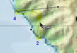


More moving control handles to be done and maybe moving one of the points. This is how the finished (for this part of the coast) shape looks...


...and that's only five points! To repeat, it's often better to draw a rough path but a complete one first, and then edit that path afterwards. The above coastline looks fine, but in making it so we broke the momentum of drawing the full path. To complete this we'd draw a new path, select two end points and do a Ctrl + J to join them together. That finished coastline might look like this:


Now with a strong texture drape it may be difficult to see a shape. You can play around with toggling Texture opacity and Selection opacity (or even toggle off Heightfield texture entirely) the to make shapes clearer. When you are initially creating the shapes, you need to see where the original lines are, but after you've created those you may not always need the texture at all.

The other contours

Of course the coastline is only one contour. In addition to this, three are higher elevations in the island's interior, and lower ones in the surrounding ocean. After a lot of extra editing, we have basic set of contours like those shown below:


Some of the shapes go outside of the map area. That's allowed, but a heightfield will only be generated within the map are. The outer rectangle (which could just as easily been an ellipse or or irregular shape) is used to mark a lowest level of the map, in relation to the contours within it. As yet, none of these shapes have a height value.

We're making this terrain to use in Opensim. In general the lowest height in that is zero, and the default sea level is set at 20m, and a maximum height in the thousands. In Leveller and other 3D terrain editors, the water level often defaults to zero. we'll keep that convention, as this is compensated for in the Export Tiles dialog box (see Part 2) with a default 20m added to the heightfields of exported tiles. So, the water level is 0, and the relative lowest level would be -20. If we set the elevation of the outside rectangle to -19 and all the other shapes have a higher elevation than that, then we won't have any issues when exporting to Opensim.

To set the elevation of a shape, first select that shape, and then Right-click to bring up the context menu, as per below:


Select Properties (you can also select Shapes > Properties on the menu) and the Properties of Selected Shapes dialog will pop up. We'll enter -19 in the Elevation field, and then select OK...
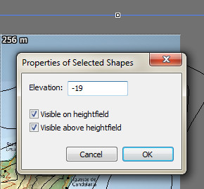


...so now we have our first shape with an elevation. We'll repeat this step on the remaining shapes. The image below shows the values I've assigned to them (though this usually wouldn't show on the map directly):


Remember that the terrain isn't really to scale (otherwise the relative elevations of the island might seem slight). The values I've chosen should highlight the creation of heightfields by using shape. Selecting the Pointer tool, either press Ctrl + A, or select Selection > Select All. Then select Shapes > Heightfield from points. The result on the map (I've toggled the Heightfield texture off for clarity) should look like this...


...and the scene pane should look a bit like this:


Don't like the elevations on the island? There's an easy way to change that.First, manually use the Pointer tool to select all the shapes used for the island:


Then go to Shapes > Modify > Span. The Spans Selected Vector Shapes dialog will appear and indicate the current range of all shapes selected.


We'll change the first value to .4 and the second to 32. Select OK, and then do another Shapes > Heightfield from points. The scene will now look something like...


The edge around the island is because we didn't select any of the ocean shapes, and the height outside the island has dropped to -19! To correct that, simply select ALL shapes (as explained above) before generating a heightfield from shapes.
Further Editing

This is just the start of creating the heightfield. In addition to using closed shapes as shown above, you can add lines and markers of various elevation to create different effects. You could add more points to improve the coastline shape, or any of the other shapes used. You can also use any of the brush tools to manually add of edit the heightfield, but that's another tutorial.
Exporting to Opensim

When you're satisfied with the result, export it to OpenSim. See Part 2 for how to do that. Here's what the above looks like imported into a 2×2 256m² demo grid:


...and here's the view:


This is still only a vague approximation of Tenerife. If you want to see something more accurate, go to Part 5!

Simpler Stuff


The above example looks complex (though the final result is fairly simple). I used Tenerife as an example because it was an interesting shape, and having a map texture from real life meant that we could judge our progress with the original. , But contour modelling doesn't have to be complex. The following document was used in Part 2. It's not based on real life maps, and is far simpler!


This 256x256 document was created by creating eight shapes, giving each a height (as shown on the map at right and then selecting all shapes followed by executing a Shapes > Heightfield from Selected Points command. Finally the water level was set using Edit > Water Level > Elevation to 20 (and when exported using Export-tiles, the height adjustment would be zero). Only eight shapes.

Importing shapes


You also don't have to create your own shapes to make a terrain, you can import them instead! Leveller will import the following vector formats: Adobe Illustrator, Arc/Info ASCII, Arc/Info Binary, BNA, CSV, DGN, DXF generalized, DXF polylines, ESRI shapefile, GeoConcept, GeoJSON shapefiles, GML,GMT, PS, IHO, Keyhole Markup, MapInfo TAB/MIF/MID, PGeo, EPInfo REC, SDTS TVP, SVG, TIGER/LINE, UKOS NTF, and X-Plane/Flightgear.

Here's an Illustrator document (Twins Contours 00.ai) I made to map the contours of a local grid that measures 6×5 1024m² regions (6144×5120px):


To import this, we'll first create a new document sized. 6144×5120px. Then, We'll run Filters > Elevate and raise the whole map to .5m. You should now see (using the Earth to Water Colour Map) a blue map. Now go to Shapes > Import shapes and the Import Vector Shape data dialog will pop up:


We'll select the Adobe Illustrator option, and find that file. Things should look like this:


Pressing OK however, only gets us this error message:


Leveller imports Adobe Illustrator, but it needs to be in Illustrator 8 format. So, we go back to Illustrator (I'm using CS6, it may be different in the CC version) and do a File > Save a Copy. Give the copy a name to identify it (Twins Contours 00 8.ai for example) and select the following options on the next dialog:
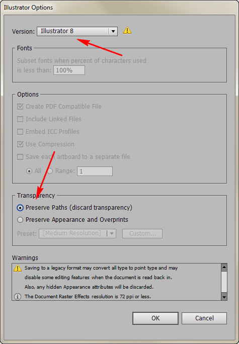


Jumping back to Leveller, select Shapes > Import Shapes again, but this select the file. Click OK, and after a delay you will see the Import Shapes from <filename> dialog:


For now we'll just select OK and proceed with the import. We wait until that's done, and should see something like this:


Your mileage might vary on this. At best, the vectors will be imported with a height value attached to them, but that value has to come from somewhere, and may not be in the program that created the vectors. Because of the wide variety of formats accepted, you can use open source (and free) programs like Inkscape to create SVG files. In Illustrator, I could have also saved the copy in SVG format as well. Use what makes sense to you.


Next time...

Part 4 of this series will deal with importing real geographical data into Leveller and preparing it for Opensim.

Monday, February 20, 2017

Leveller for OpenSimulator (part 2)

Exporting from Leveller to Opensim

This tutorial looks at working with Leveller (a powerful 3D terrain editor for windows from Daylon Graphics) and OpenSimulator (Opensim). Part 1 explained how to import terrains from Opensim into Leveller. This part explains how to export heightfields in Leveller back into Opensim.

OpenSimulator Regions used

This part uses the four regions of test00, test01, test10, and test11 to demonstrate exporting terrains from Leveller back into the grid.


The listing for these regions likes a bit like...


...however the positions are only important  when importing the heightfields files using load-tile command.

Exporting single regions

To demonstrate exporting single regions we'll be using the following example from Leveller...


This 256x256 document was created by creating eight shapes, giving each a height (as shown on the map at right and then selecting all shapes followed by executing a Shapes > Heightfield from Selected Points command. Finally the water level was set using Edit > Water Level > Elevation to 20.

Exporting to In-World

You can export the above Leveller document as a RAW file for loading in-world. To do this, select File > Export and pick the Second Life option. After selecting a file to save to (it needs to be an existing RAW file, but you can easily copy the file and rename that copy) you might see something like this:


If the document has any heights less than zero you will get an error and the export will fail. It's best to play around with Original Elevations and Use per-pixel scaling. Once you've exported the file, you can go in-world and load it via your viewer.

You have to be the owner of the region in order to upload the raw file. Go to the Region / Estate dialog box and select the Terrain tab. You'll see something like this:


Select the Upload RAW terrain button, select the file and the terrain will be loaded. It should look something like this:


The submerged area above is roughly at 20m and matches the default water level. However on the original Leveller document that coastline contour is 20.6, and clears the waters. There's some trade off and inaccuracy using the .raw format. Compare this with exporting in .ter format (below). 
 

Server commands for saving terrains

The following two methods use server commands to save region's terrains. Server commands are made within the Opensim console. These examples are taken using ConEmu, a "Windows console emulator with tabs, which presents multiple consoles and simple GUI applications as one customizable GUI window with various features". ConEmu, rather than the Windows command line was used, as ConEmu behaves more like a Linux terminal, with the user being able scroll back through previous lines and reports, and use the up arrow to see (and then edit) previous commands. Users are also able to copy and paste from and to the console easier that with the standard  DOS prompt, and key shortcuts and colour schemes can be set for convenience.  All this makes using the Opensim console a lot easier for a Windows user. Other OSs may have their own equivalents. ConEmu was used as I predominantly use Windows and Windows apps (and hence Leveller).

For single regions

Leveller can export a heightfield to Opensim  simply by exporting using Terragen format (.ter). To do so, select File > Export and select the Terragen option. After selecting a file to save to, the dialog should look something like this:


To load the terrain for a single region you must first change to that region. You do this by using the "change region" command. For example, to go to the test00 region we'd type...


change region test00 [ENTER]

...and the console prompt should now show...


Region (test00) #

If it doesn't, you may have mistyped the name of the region. Making typos like that can create unexpected errors! Assuming you have now selected the region, You would use the "terrain load" command to save that to a particular file. For example...


terrain load N:\OpenSim\HeightFields\Leveller\Tutorial\in-world\test00.ter

...would load the terrain from the test00.ter file in that directory (you need to put quotes around a file path name if it has spaces in). The format of the file save is determined by the extension used as follows:
Extension File Format
.r32/f3232bit RAW,
see RAW, 8 bit, 16 bit, and 32 bit explained
.terTerragen heightfield,
see Terragen™ Terrain file specification
.rawlinden labs/Second Life RAW,
see Tips for Creating Heightfields and Details on Terrain RAW Files
.jpg/jpegJoint Photographic Experts Group  image format.
.bmpdevice independent BitMaP
.pngPortable Network Graphic
.gif Graphics Interchange Format
.tif/tiffTagged Image File Format
.gsdgeographic survey data file
As you can see above, the example file was loaded in the Terragen format. The reasons for choosing that format are that it is a heightfield format rather that a graphics format, and that Leveller uses a modified Terragen format for its documents. If this is successful the console should look something like this:

  After loading the file in the region it'll look something like this in Opensim:


Here's a comparison between .raw and .ter exports, using the in-world map:


A good work practice is to use the Leveller document as a master file, and to make changes in that, rather than later re-import that region a second time to make modifications. Here's the above region re-imported back into Leveller using a raw file generated in-world...


...not pretty is it? Most of the bumpiness and abstraction is caused by using an image format to save heightfield data. If you own or rent a region but can't access the console for that grid, see if you can get the administrator to use terrain save (see part 1) and terrain load to for you (using .ter format), rather than using a .raw file.

For tilesets

In Opensim you can create regions that are square with dimensions in multiples of 256, for example 256x256, 512x512, 768x768, and so on. However at present you cannot have two regions of different sizes adjacent, without having issues  with one or more of those regions. So, in general you won't see a 256x256 region next to a 512x512 region, but you may see a string of 256x256 or larger regions together. A "tileset" is a collection of adjacent or connected regions of the same size. The following is a 512x512 example we'll be using in Leveller (which will be a 2x2 tileset of 256x256 regions):


You can just see the 256m grid lines on the map. This is also an example of  the MicroDEM colour scheme. Leveller allows you to change display colours for heights. It's also an example of me playing around with different tools!

Export a Leveller document as a PNG

Leveller can export the above as a PNG file. To do so, use the File > Export command and select the PNG option. After choosing a filename, and opening option, you should see something like this:


After OKing that, the following gets created in that directory:


The .wld and .xml  files are created by Leveller in the process of making the PNG. And the PNG looks something like this:


Load-tile command

The single PNG file created above for a tileset, can be loaded into Opensim using the terrain load-tile command in the console. This only works saving to a PNG file. The syntax is:
terrain load-tile <filename> <tile width <tile height> <xstart> <ystart>

...and where: <filename> is the file name of the of the saved file (e.g. 2x2tileset(default).png), and <tile width <tile height> is the width and height of the tileset, and <xstart> <ystart> are the grid's x and y location of the south west corner of the tileset (e.g. 1102 1000 for the sample island is the test00 region). However, you must also select each region in the tileset in sequence, and then repeat the command for that image, in order to load the section of that PNG that corresponds to the region selected.

For example, to load the PNG image above into test00, test01, test10 and test11, you would need to do the following commands:


Unlike the save-tile command (see part 1), you can load images that are not just in the /bin directory! The result of the above commands is...


Now this looks like the heightfield alright, but it seems to be a bit exaggerated, and what's happened with the water level? Comparing the Leveller map with the Opensim map, we can see this more clearly:


The water level hasn't changed in Opensim so it must be something to do with the format of the PNG (16bpp and the map elevations range). You can either go back to Leveller and fiddle around with the export settings (and check the document for silly errors like setting the water level at the wrong height, though in the above example it was set to 20.0008m in Leveller), or you can fiddle around with the height field either in-world, or via the console. If you want to go via the console method, select the region and try playing around with the following commands:
terrain elevate <num>
Raises the current heightmap by the specified amount.
terrain lower <num>
Lowers the current heightmap by the specified amount.
terrain multiply <num>
Multiplies the heightmap by the value specified.
terrain rescale <min> <max>
Rescales the current terrain to fit between the given min and max heights
terrain revert
Loads the revert map terrain into the regions heightmap.
In this instance I was able to fix the height issue buy using terrain lower 11 in each region. The result looks like...


But, the solution won't always be to do that command - it varies depending on the terrain. There is a third alternative, and that's to use the Export tileset feature of Leveller. 

Exporting tilesets from Leveller

Leveller now has an Export Tileset option which will automatically export a Leveller document as a set of Terragen formatted files suitable to be imported using terrain load within Opensim. To create this, use File > Export Tileset. The following dialog will appear:


There are several sets of options on this dialog. Output filename allows you to select both the directory to save the tile files in, and a "base name" to use how those files are named. The directory you use for a tileset export should either be empty, otherwise confusion might result.The base name (e.g. if you enter test.ter, the base name is test) is added to codes generated by Leveller to indicate where in the tileset the file goes. For example test_x0_y2.ter should be loaded into the region in the bottom row (numbering starts with 0) and 3 columns from the left. See below for an efficient way of doing this.

Tiling has two ways to decide split up the document into tiles - by px per tile, and by the number of tiles across and down the tileset. If you always use the same size regions (and they'll always be square in Opensim) then you might just just use that option (e.g. 256), but choosing the second might be easier if you're working with larger sized regions. The Elevation offset is added to the the heightfields of the exported files, and works the opposite way to the same option on Import Tileset. It defaults to 20 which matches the default water level in Opensim, but can be changed.

The water height may be an issue with the current example. Above I mentioned it was set to 20.0008m (some minor rounding errors). If we're using the Export Tileset method, that expects the water level to be at 0m in Leveller. Now we could either go back into Leveller and drop the heightfield by 20m, and then then set the water level to 0m. To drop the whole heightfield we'd either select all (or none) and then do Filter > Elevate and use the following settings:


Setting the water level is as simple as Edit > Water lever > Elevation and entering 0.0 m (works better than just plain 0). Now that might a good thing to do if you're working on several documents and most of them have the Water Level set to 0. However, if we just wanted to export that tileset now and doing that later, we could just enter 0 m for the Elevation offset instead! Assuming that we do, here's what the dialog might now look like:


After you OK that, the files in the Export sub-directory will look like this:


The next step is loading the files into Opensim using the terrain load command as detailed above. You simply change regions and then terrain load for each. The following is how this would look in the console for the example tileset...


...and here's the result in-world:


No adjusting needed!


Part 3 shows how to make terrain using shapes.